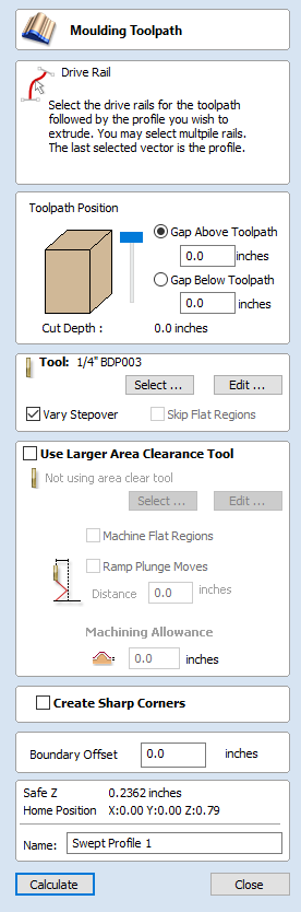
VCarve Toolpath

This icon opens the V-Carving Toolpath form which is used to specify the type of carving required, tooling details, cutting parameters and name for the toolpath.
Cutting Depths
Start Depth (D) specifies the depth at which the V-Carving toolpath is calculated, allowing V-Carving / Engraving to be machined inside a pocket region. When cutting directly into the surface of a job the Start Depth will usually be 0.0. If the V-Carving / engraving is going to be machined into the bottom of a pocket or stepped region, the depth of the pocket / step must be entered. For example, to carve or engrave into the bottom of a 0.5 inch deep pocket, the Start Depth = 0.5 inches
Flat Depth (F)
Checking ✓ this option limits the depth that the tool(s) will machine to, and is used for Flat Bottomed Carving and Engraving.
When No Flat Depth specified the toolpath will be calculated to carve or engrave to full depth as shown below. Multiple z level passes will be automatically calculated where the tool needs to cut deeper than its Pass Depth specified in the Tool Database.
No Flat Depth
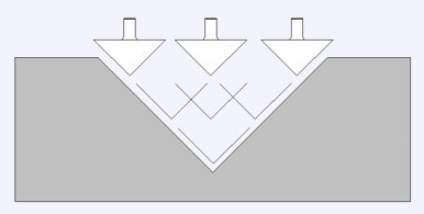
Single tool machines the complete job.
Multiple z level passes calculated using the Pass Depth specified for the selected tool.
Clicking the option for Flat Depth and entering the required depth will result in flat pocket areas being machined where the width between vectors would result in the tool cutting deeper than the specified Flat Depth.
Flat Depth
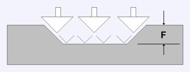
Complete toolpath is calculated using a single V-Bit or Engraving tool.
Flat Depth Using 2 Tools
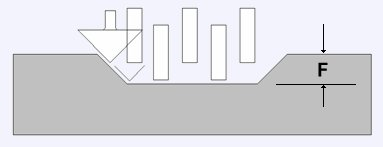
End Mill to create the flat pocket regions followed by V-Bit or Engraving tool to cut the detail and corner regions
V Tool
Clicking the button opens the Tool Database from which the required VCarving or Engraving Tool can be selected. See the section on the Tool Database for more information on this.
Clicking the button opens the Edit Tool form which allows the cutting parameters for the selected tool to be modified, without changing the master information in the database. Note that Ball nosed tools can also be used to VCarve designs.
Use Flat Area Clearance Tool
Check ✓ this option if you wish to use an End Mill, Ball Nose or Engraving cutter to machine the large open regions of a design. Note that this option is only available when Flat Depth is selected. If no tool is selected here but Flat Depth is specified then the selected VCarving tool will be used to clear the flat areas as well as for the VCarving.
Clicking the button opens the Tool Database from which the required End Mill or Engraving Tool can be selected.
Clicking the button opens the Edit Tool form which allows the cutting parameters for the selected tool to be modified, without changing the master information in the database.
Flat Area Clearance
This section of the form allows you to choose the strategy which will be used to clear the flat bottomed area with the Flat Area clearance tool. These options are the same as those found on the pocketing form.
Ramp Plunge Moves
If this option is selected ramps are added to the plunge moves for the pocketing toolpath.
Use Vector Selection Order
If this option is checked, ✓ the vectors will be machined in the order you selected them. If the option is not checked the program will optimize the order to reduce machining time.
General Toolpath Settings
This section of the toolpath form is common to a number of toolpath strategies.
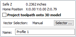
Safe Z
The height above the job at which it is safe to move the cutter at rapid / max feed rate. This dimension can be changed by opening the Material Setup form.
Home Position
Position from and to that the tool will travel before and after machining. This dimension can be changed by opening the Material Setup form.
Project toolpath onto 3D Model
This option is only available if a 3D model has been defined. If this option is checked, ✓ after the toolpath has been calculated, it will be projected (or 'dropped') down in Z onto the surface of the 3D model. The depth of the original toolpath below the surface of the material will be used as the projected depth below the surface of the model.
Vector Selection
This area of the toolpath page allows you to automatically select vectors to machine using the vector's properties or position. It is also the method by which you can create Toolpath Templates to re-use your toolpath settings on similar projects in the future. For more information, see the sections Vector Selector and Advanced Toolpath Templates.
Name
The name of the toolpath can be entered or the default name can be used.